Overlanding Rig - Panda
Auxiliary Electrical System

Here's where it all started. Two years' worth of electronics additions - a complete rat's nest. This single fuse box is distributing power to a full suite of cameras and several lights.
Continuous upgrades required a new, modular system that could organize and consolidate the current accessories as well as several planned additions in the future.
A secondary goal was to optimize wire routing, especially through the firewall. Previously, every new accessory had its own power wires passing through the firewall.


First thing's first - the old electrical system needs to be forcibly removed from the vehicle. That means all the old accessory switches, camera wires, video splitters, and relays need to be taken out so the system can be comprehensively rebuilt.
You can see how many wires ended up coming through the firewall and going to the dash to cover two years' worth of mods.
The next step was to lay out the components that would be necessary to organize the electronics fully. There was space above the starter battery, so I began by cutting out cardboard mockups to see what kind of real estate I would be working with. This would be the beginnings of creating an MCO (mechanical control outline).
The parts shown here include two busbars (for +12V and GND), a relay box with in-line fuses, a fuse block retained from the old system, and a terminal block.
One thing I took into consideration here was accessing the starter battery terminals with the platform installed.


After the platform was sized and shaped properly, and all components had found their mounting locations, I moved onto implementing the design in a robust material - aluminum. I had 3mm aluminum plate readily available, so I traced the cardboard template and got to work.
The aluminum plate was cut with a jigsaw and deburred with a beltsander. First test fit of the platform is a success! I did end up going back in with a dremel to improve the fitment around the positive terminal cap.
Added some M6 standoffs to the threaded ends securing the battery clamp. These standoffs locate and retain the new auxiliary electrical system tray.


The different components were test fit on the aluminum plate in order to start looking at wire routing. I needed to utilize several nylon standoffs so wires could be routed under some of the bulky components. I also added a master switch for the whole system - for maintenance purposes.
Test fit the plate with all components mounted inside the engine bay. I needed to make sure that there would be no interference when the hood was closed.
Wiring up all the electrical components as well as the camera system and accessories was no simple task. Several lights had significant power draw and needed relays. The camera system switches alone needed 32 signal inputs for the 8 cameras. I made this schematic to keep it all organized - and to make sure I retained my sanity during the wiring process.
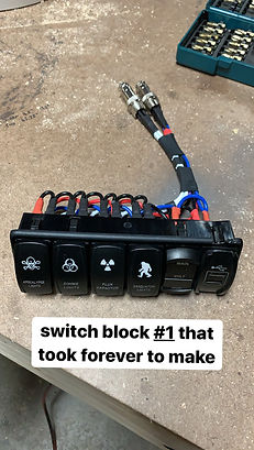
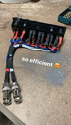


Two switch blocks are necessary to control all the lighting, power a couple of USB ports, and display main and auxiliary battery voltages. I wired up all the switches and other modules per the schematic I created. Wiring was optimized by consolidating accessory power, switch power (ignition activated relay), and ground, With the wiring configuration, these switches will light up only when the car is turned on, but will be able to control accessories regardless of the car being turned on or off. I implemented aviation connectors for ease of assembly and reworkability.


Wiring the relay box required heavy reliance on the schematic I created. I color coded the different signals going to each of the relays for ease of wiring. In the end, I had a consolidated power in, consolidated ground, signal inputs for 6 relays, and signal outputs from 6 relays. The purple wires receive either a 0 or +12V signal depending on switch state, and the blue wires accordingly provide power for any connected accessory rated up to 30A* (*40A rated by relay, 30A rated by 12AWG wire).


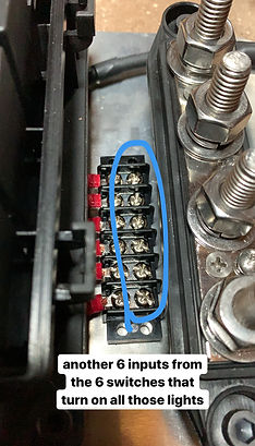
All the in-line fuses and relays were installed into the relay box. One of the relays is activated by ignition power, so that any accessories/cameras that require ignition power can run on a 40A circuit instead of the original 15A cigarette lighter fuse. The other five relays feed high power accessories.
All six relay outputs are connected to a terminal block for simplified accessory connection. All six relay inputs are connected to a different terminal block for simplified switch input.

The busbars were populated with +12V power and ground and connected to larger accessories such as the air compressor in the background, a 1500W power inverter, and the fuse box/relay box.


Pulled wires through the firewall - sufficient for 6 switch inputs for the relays, +12V battery power, and the ignition activated relay output. These need to be wired up on both ends.
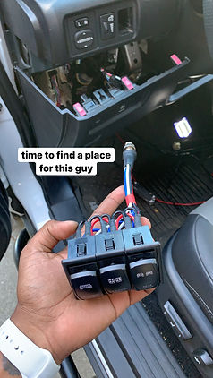

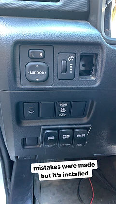
Mounted the 3-gang switch for roof rack mounted lights to the dash.

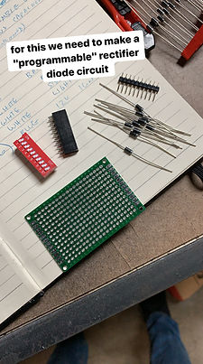

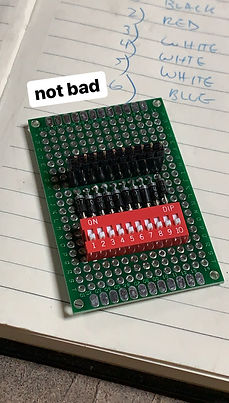
Created a simple perf board circuit that can activate multiple relays at once without any backfeed. I used diodes to isolate the master apocalypse switch so the original discrete switches can still activate their own circuits. The red micro switch block allows me to configure which circuits are activated by the master switch.


Completing the wiring in the dash required organization - there were many signal wires and several camera outputs that needed to be organized. To do so, I decided to build an internal panel.


Created a cardboard mockup to check fit in the center console. The panel is intended to mount connectors for the camera switches, house USB ports, and act as an enclosure for the analog camera switcher input ports.


Once the cardboard mockup was complete, I began fabricating a rigid panel out of ABS. This allowed for easy mounting of the USB ports and camera inputs. Assembly into the center console was slightly more difficult but there was still a comfortable flight path.


Mounted two 6 pin aviation connectors onto the panel to connect the camera system to the switches. Since the camera switches are mounted to the center console cover, the service loop needs a disconnect point when the center console cover gets removed for maintenance or upgrades.

Here's the completed panel with all connection points. One pigtail gets connected to the wiring harness for the camera integration circuit. The other pigtail powers the four USB ports that were installed in the panel.
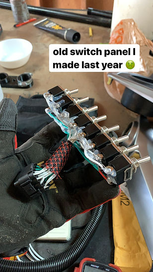

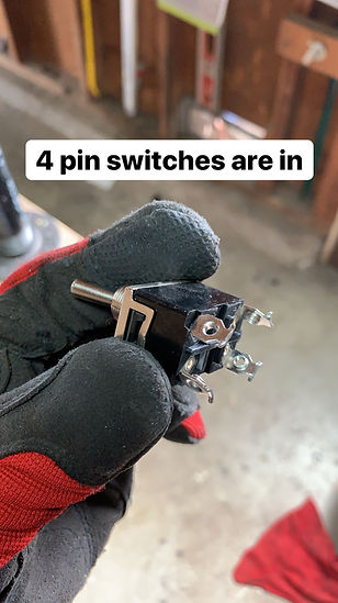
The next step was rewiring the camera toggle switches. My previous attempt was clumsy and I didn't fully understand the electrical requirements so several signals were duplicated. One switch was dedicated to activating the system while the rest activated unique cameras. With my new schematic, I planned to migrate from eight 2-pin switches to seven 4-pin and one 2-pin switches that would each activate the camera system on their own. This way, I could squeeze an extra camera into the switch lineup.


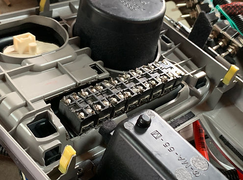
The new 4-pin switches need some modification to fit the same pitch that the 2-pin switches did. Some time on the beltsander was sufficient to reduce the width so they fit into the original enclosure.


I ended up needing to get a respirator during this step due to the significant amount of solder fumes that were blowing into my face. It was definitely worth it though! Utilizing my schematic, I was able to efficiently hook up 3/4 pins from all the switches to common signals.


Once the switches were all wired, I created a long service loop with two 6 pin aviation connectors at the end, to plug into the original panel we created to mount inside the center console.

One more beauty shot of the center console cover with all camera toggle switches installed, plus our consolidated panel for USB power and camera inputs. Time to assemble everything to the vehicle and test!


Wiring is all done and the center console is closed up! I'm extremely happy with how clean the integration is. Thanks for reading!
