Overlanding Rig - Panda
Camera System

As I began to go on more offroading trips (occasionally without a copilot to spot me), I imagined how convenient it would be to have a camera system strategically monitoring locations of the vehicle that might encounter obstacles. Finding a plug-and-play camera activation system (Anytime Backup Camera) that allowed me to toggle the backup camera on and off as well as added a second switchable camera input was a catalyst for this project. While many are satisfied with being able to control a front and back camera, I knew I wanted to have several more cameras underneath and to the sides of the vehicle.


The camera system consists of two major components - the Anytime Backup Camera harnesses and an analog audio/video switcher. The harness plugs into the OEM head unit and has two switchable inputs - one for a backup camera and one for an auxiliary camera. My initial setup plan was to keep my OEM backup camera hooked up to the backup camera input and connect the analog audio/video switcher with 8 inputs to the auxiliary input. However, the addition of a rear-mount spare tire blocked the OEM backup camera and required a new camera to be installed - quite convenient with this system.


Due to space constraints in the center console, I needed to strip down the video switcher to only the critical components. So began the disassembly and analysis.
Once I took the cover off, I saw that there were eight 8-pin switches. The first step was to figure out what pins shorted when the switch was activated. A quick continuity probe with a multimeter showed that each grouped pair of pins was shorted. Teardown of one of the switches confirmed.


The next step was to figure out which pair of pins was for the video line. I assumed that the four pairs represented audio left and right, video, and a common ground. To check, I put a male-to-male composite video adapter in one video input and the video output. I shorted those together and checked which pins were shorted on an activated switch, as shown below.


Once I figured out which pins I needed, I began stripping away unnecessary components. I desoldered all the push-button switches since I was planning on using my own switches to toggle the cameras. The enclosure was entirely removed - leaving just the signal inputs/outputs and switch pin vias. I did further reduce the size by cutting away the audio inputs since they were unnecessary for this particular application.


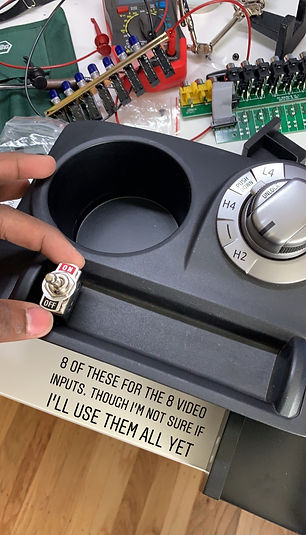
The 4Runner came with a perfect location for toggle switches - right on the center console. I was planning on installing eight switches - one for the backup camera, one to activate the system for the remaining cameras, and six for any other cameras. The toggle switches I sourced ended up being the perfect size for 8 spanning the opening evenly.


Quickly trimmed away some excess plastic on the center console cover that was blocking the bottom of the tray in which the switches needed to be installed.


Made a template to drill the eight holes for the switches. Each switch is panel-mount style - 1/2" threaded neck that mounts to the plastic with a thin nut.


Switches mounted! I was surprised at how well it all integrated into the OEM panels.


Wired the switches to the analog video switcher PCB. The first iteration was clumsy and lacked any service loop. I quickly switched over to a lengthy cable with a 16 pin automotive connector for easy maintenance access.

The final iteration of the wiring was optimized so all common lines were consolidated to a single wire (an obvious optimization but my previous iterations lacked the planning to do this).


The wiring of all cameras continued. Power was distributed via two busbars. One of the more interesting tasks was wiring the switches to turn on the backup camera and turn on the rest of the camera system. The peculiar thing about the camera system is that the auxiliary camera needs the backup camera switch to be on. In order to simplify the controls, both switches were connected together with a diode to prevent backfeed.


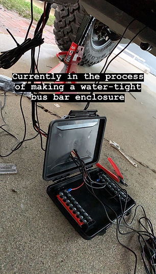
The wiring of all cameras continued. Power was distributed via two busbars. One of the more interesting tasks was wiring the switches to turn on the backup camera and turn on the rest of the camera system. The peculiar thing about the camera system is that the auxiliary camera needs the backup camera switch to be on. In order to simplify the controls, both switches were connected together with a diode to prevent backfeed.


All the cameras that are currently installed. There are three cameras underneath - bottom-center facing forward, bottom-center facing back, and bottom-rear facing forward. One camera is installed underneath the rear spare tire (used as a backup camera). Finally, we have a front-facing camera on the grille.
Cycling through the cameras! Everything is cleanly integrated into the OEM head unit.


Here are a few other examples of the camera system in action. Hover over the image to play the video!


After a mishap with vehicle recovery where I backed into my rescuer due to obstruction of the rear window, I decided I needed a better rear view mirror. I sourced an LCD rearview mirror replacement that had a constant camera feed to replace my regular mirror. I fabricated a mount for the spare tire swing arm so I could position the camera between the spokes, and ideal location behind my rear window.

Final camera mount position for the rearview mirror. It's solid!
The camera mounted in the rear spare tire outputs to the LCD display mounted to the original rearview mirror. Given that the rear window is now blocked by the spare tire and rear seat headrests, this is a necessary upgrade to be able to see what's behind the car.